Plumbing Hydraulics, Sanitary Drainage & Pumping Suite
Uniform Plumbing Code (UPC) and International Plumbing Code (IPC) water pipe velocity limits, Total Dynamic Head (TDH) pump horsepower, IS 2470 dual-chamber septic tanks, and cable tray containment.
Pump Total Dynamic Head (TDH) & Brake Horsepower
Centrifugal & Sump
Real-Time Mathematical Derivation:
1. Total Dynamic Head TDH = 145 ft (44.2 meters)
2. Water Horsepower (WHP) = 1.28 HP | Brake Horsepower (BHP) = 1.83 HP
3. Selected Commercial Motor = 2 HP (1.49 kW)
Hydraulic & MEP Result
2 HP Pump
TDH: 145 ft | Power: 1.49 kW
Capacity Utilization MeterSafety Margin
IPC & IS 2470 Hydraulic Rules of Thumb
Maximum Supply Velocity:≤ 8.0 ft/sec (prevents water hammer)
Minimum Fixture Pressure:≥ 20 psi (1.4 bar residual)
Septic Tank Length-to-Width Ratio:2:1 to 3:1 (IS 2470 standards)
Gravity Drain Minimum Slope:1/4" per foot for ≤2.5" pipes
Institutional Infographic: Plumbing, Sanitary Drainage & Pumping Systems
0% Blur Vector Clarity
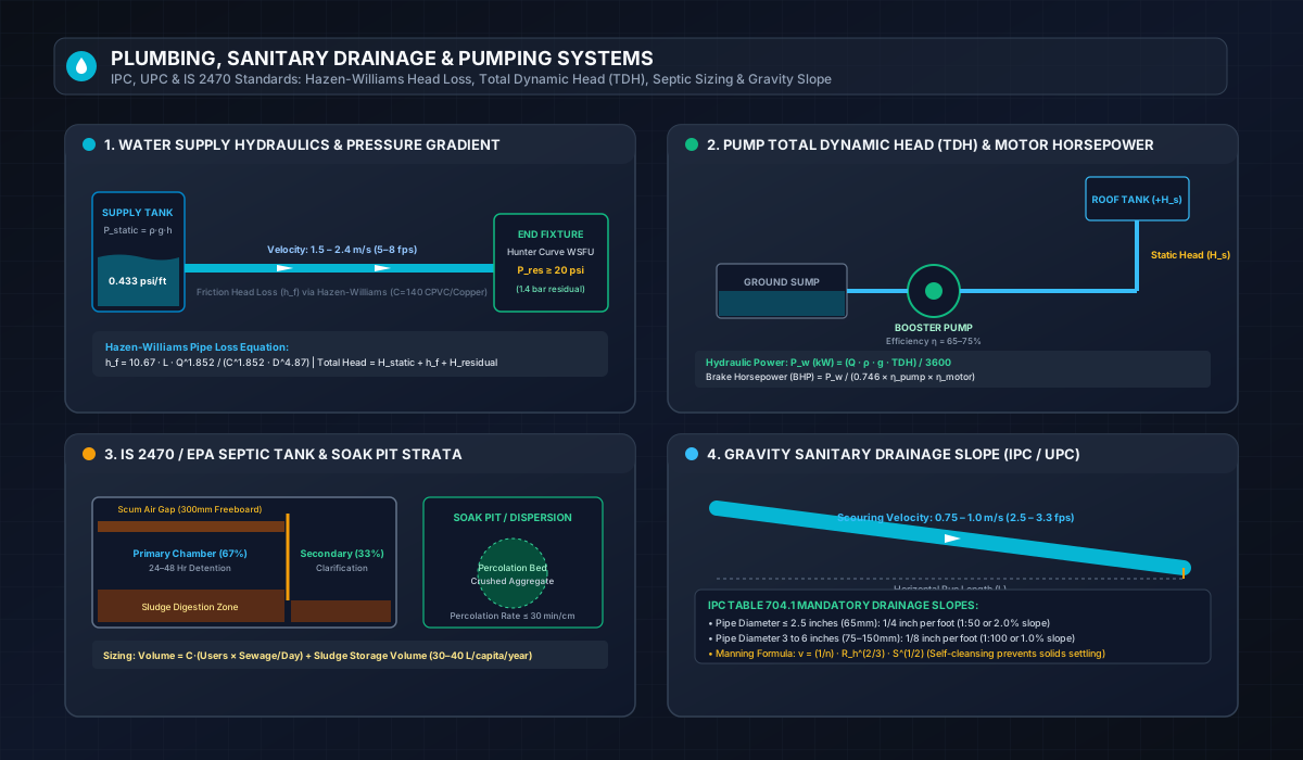
Visual technical reference illustrating Hazen-Williams pipe loss gradients, Total Dynamic Head pump elevation, dual-compartment septic tank cross-sections, and IPC gravity drainage slopes.
Professional guidelines adhering to the International Plumbing Code (IPC), Uniform Plumbing Code (UPC), and Indian Standard IS 2470 Code of Practice for Design and Installation of Septic Tanks.
1Water Supply Hydraulics & Hunter's Curve Probability Modeling
Designing a building’s potable water distribution network requires calculating peak simultaneous demand. Because plumbing fixtures (washbasins, water closets, showers, kitchen sinks) operate intermittently rather than continuously, sizing pipes for 100% connected fixture capacity would result in drastically oversized pipes, stagnant water quality degradation, and exorbitant copper/CPVC procurement costs.
In 1940, Dr. Roy B. Hunter of the National Bureau of Standards developed the Water Supply Fixture Unit (WSFU) system based on binomial probability distribution. Each fixture is assigned a weighted numerical unit reflecting its discharge flow rate, duration of a single flush/cycle, and average frequency of use. Total WSFUs are converted into peak design flow (GPM) via Hunter's Curve, which distinguishes between flush-tank fixtures and flushometer valves.
Under IPC Section 604, water velocity in copper and plastic supply piping must be restricted between 1.5 and 2.4 m/s (5 to 8 ft/sec). Velocities exceeding 8 ft/sec induce hydraulic cavitation, acoustic pipe singing, erosion-corrosion of thin-wall fittings, and damaging water hammer shockwaves during quick-closing solenoid valve shutoff.
2Total Dynamic Head (TDH) & Centrifugal Booster Pump Sizing
When municipal mains pressure is insufficient to reach upper storeys or roof-level break tanks, booster pump sets are required. Sizing a centrifugal pump requires accurate determination of Total Dynamic Head (TDH):
Static Head (H_static): Vertical elevation rise from suction liquid level to highest delivery point.
Friction Head Loss (h_friction): Ohmic resistance of pipe walls and equivalent lengths of elbows, tees, check valves, and strainers via Hazen-Williams.
Residual Fixture Pressure (H_residual): Minimum pressure required at the topmost fixture (typically 20 psi ≈ 46.2 feet of water head).
Where centralized municipal sewerage infrastructure is unavailable, on-site septic tanks provide primary anaerobic digestion and physical sedimentation:
Tank Compartmentalization (2:1 Ratio)
Under IS 2470 (Part 1), the primary settling chamber must comprise two-thirds (67%) of the total liquid volume, while the secondary polishing chamber constitutes one-third (33%). An inverted T-pipe or slotted baffle wall ensures that floating grease scum and dense settled sludge remain isolated in the primary compartment.
Soil Percolation & Soak Pits
Effluent exiting the secondary chamber contains dissolved organic solids requiring aerobic percolation through graded aggregates into porous subsoil. Percolation tests must confirm a drop rate ≤ 30 min/cm. If soil is dense clay, evapotranspiration mounds or sub-surface sand filters must be constructed.
Unlike pressurized water supply pipes, building sanitary sewers operate under gravity open-channel flow conditions. The slope must be engineered precisely:
Insufficient Slope (< 1:100): Water velocity drops below 0.6 m/s (2.0 ft/sec), causing suspended fecal solids and toilet tissue to settle along the pipe invert, leading to recurring blockages.
Excessive Slope (> 1:25): Water accelerates rapidly and races ahead of heavy solids, leaving stranding waste behind.
Standard IPC / UPC Optimum Slope: 1/4 inch per foot (1:50 or 2.0%) for pipes ≤ 2.5 inches; 1/8 inch per foot (1:100 or 1.0%) for 3-inch to 6-inch pipes maintains ideal self-cleansing velocity of 0.75 to 0.90 m/s.
About Water Pump Calculator
Comprehensive plumbing, sanitary hydraulics, and containment engineering workstation. Size water supply distribution piping via WSFU Hunter's Curve, calculate dynamic friction head loss, determine residential septic tank and drainfield dimensions, evaluate gravity sewer Manning pipe slopes, compute booster pump Total Dynamic Head (TDH), verify cable tray fill percentages, and calculate earthing ground rod resistance to IPC, UPC, and IEEE 80 standards.
Why this page helps
Eliminates severe hydraulic problems such as water hammer, pipe cavitation, scouring erosion, and low fixture terminal pressure
Ensures environmental protection and public health compliance for on-site wastewater disposal and septic leach fields
Delivers comprehensive MEP trade calculations spanning hydraulic, drainage, cable containment, and ground safety in a unified suite
How to use it well
Select your target hydraulic or MEP engineering tool: Water Supply Pipe Sizing, Hydrostatic Pressure & Head Loss, Septic Tank Volume & Drainfield, Gravity Drainage Slope, Booster Pump TDH, Cable Tray Fill, or Earthing Pit Resistance.
Enter primary plumbing or containment parameters: fixture unit load (WSFU or DFU), flow velocity targets (typically 4 to 8 ft/s to avoid water hammer and scouring), or soil percolation rate (MPI / minutes per inch).
Specify conduit or hydraulic dimensions: pipe internal diameter, absolute roughness coefficient (Hazen-Williams C-value or Manning's n), pipe run length, vertical static elevation lift, and fitting equivalent lengths.
Review hydraulic velocities, Reynolds numbers, Manning flow depths, Total Dynamic Head (TDH), brake horsepower (BHP), and electrical ground earth loop impedance.
Cross-reference results with International Plumbing Code (IPC), Uniform Plumbing Code (UPC), EPA septic regulations, and IEEE 80 earthing safety guidelines.
Export institutional MEP engineering calculation reports to PDF, print plumbing submittals, or download raw structured data in CSV, JSON, or TXT.
Expert tips
To prevent pipe scouring, erosion-corrosion, and disruptive water hammer, design domestic potable water supply pipes for a maximum fluid velocity of 8 ft/s (2.4 m/s) in cold water lines, and cap hot water lines at 5 ft/s (1.5 m/s) per Copper Development Association guidelines. For gravity drainage lines, maintain a minimum scouring velocity of 2 ft/s (0.6 m/s) with a minimum 1/4 inch per foot (2%) slope on pipes 2-1/2 inches or smaller to prevent solids deposition.